
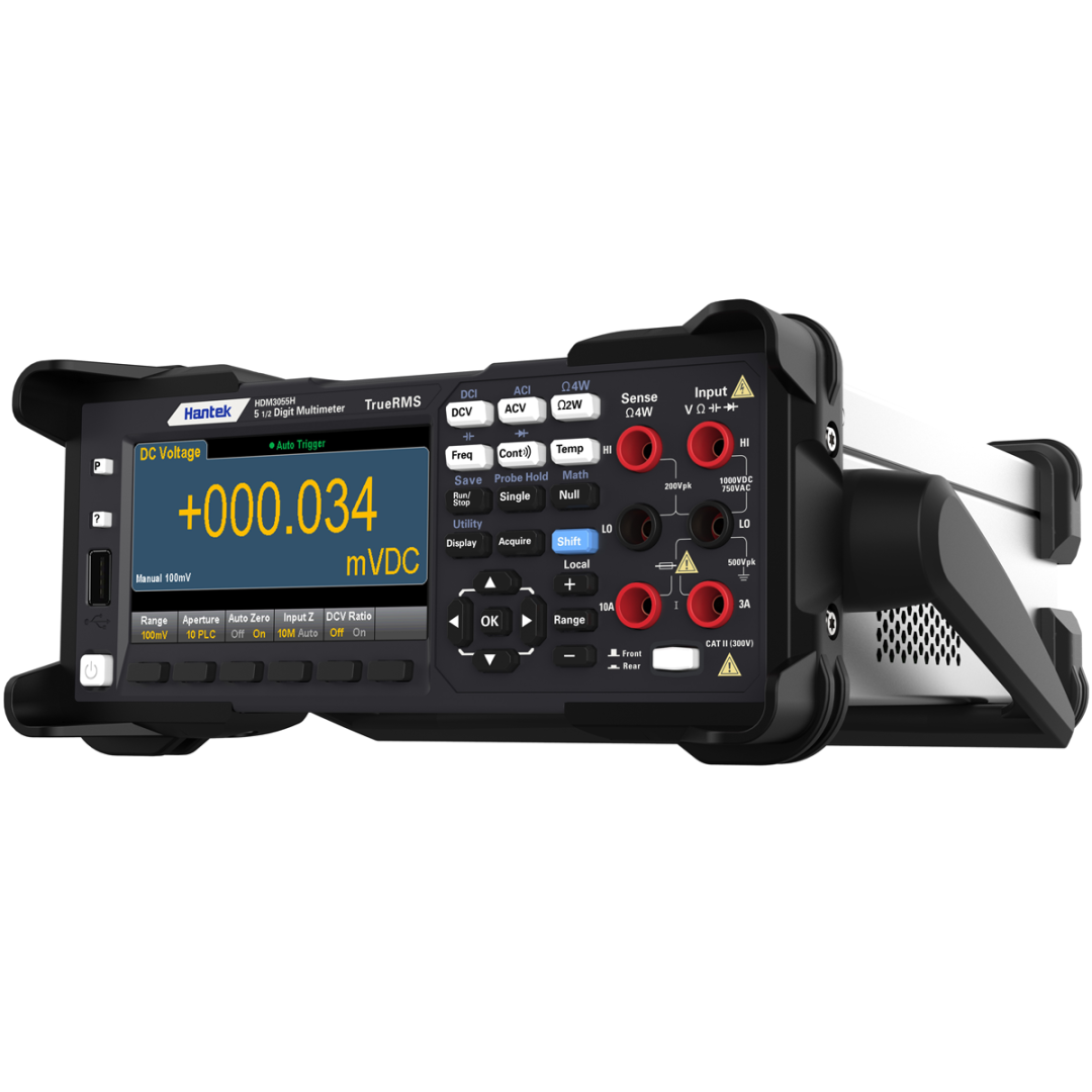
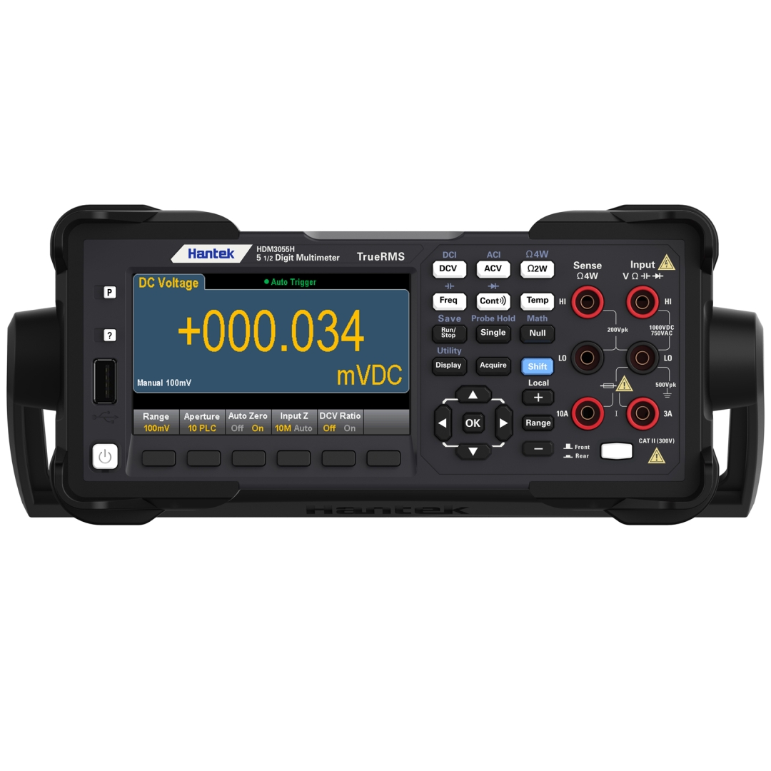


HDM3055 1 μV Yüksek Çözünürlüklü 5 1/2 Reading Multimetre
KARGO BEDAVA
19.680,55 TL (KDV Dahil)
39.361,10 TL
| DC precision technical index: ± (% reading + % range) | ||||
| Range1/Frequency | Test current or Load voltage | Input impedance | 1 year | Temperature coefficient/°C |
| 23℃± 5 °C | 0 ℃-18 ℃ | |||
| DC voltage | 28 ℃-55 ℃ | |||
| 100 mV | — | 10 MΩ or>10 GΩ | 0.018 + 0.008 | 0.0020 + 0.0008 |
| 1 V | — | 10 MΩor>10 GΩ | 0.015 + 0.005 | 0.0015 + 0.0008 |
| 10 V | — | 10 MΩ | 0.015 +0.005 | 0.0020 + 0.0008 |
| 100 V | — | 10 MΩ | 0.015 + 0.005 | 0.0020 + 0.0008 |
| 1000 V | — | 10 MΩ | 0.015 + 0.005 | 0.0020 + 0.0008 |
| resistance2 | ||||
| 100 Ω | 1 mA | — | 0.050 + 0.008 | 0.0060 + 0.0008 |
| 1k Ω | 1 mA | — | 0.050 + 0.008 | 0.0060 + 0.0005 |
| 10 kΩ | 100 μA | — | 0.050 + 0.005 | 0.0060 + 0.0005 |
| 100 kΩ | 10 μA | — | 0.050 + 0.005 | 0.0060 + 0.0005 |
| 1 MΩ | 5 μA | — | 0.060 + 0.005 | 0.0060 + 0.0005 |
| 10 MΩ | 500 nA | — | 0.250 + 0.005 | 0.0250 + 0.0005 |
| 100 MΩ | 500 nA || 10 MΩ | — | 2.000 + 0.005 | 0.3000 + 0.0005 |
| DC | ||||
| 100 μA | <0.02 V | — | 0.050 + 0.015 | 0.007 + 0.0015 |
| 1 mA | <0.2 V | — | 0.050 + 0.007 | 0.007 + 0.0010 |
| 10 mA | <0.02 V | — | 0.050 + 0.015 | 0.008 + 0.0015 |
| 100 mA | <0.2 V | — | 0.050 + 0.007 | 0.008 + 0.0010 |
| 1 A | <0.1 V | — | 0.100 + 0.015 | 0.012 + 0.0015 |
| 3 A | <0.3 V | — | 0.250 + 0.007 | 0.015 + 0.0010 |
| 10 A | <0.02 V | — | 0.250 + 0.007 | 0.015 + 0.0010 |
| Breakover3 | ||||
| 1 kΩ | 1 mA | — | 0.100 + 0.100 | 0.005 + 0.005 |
| Diode test4 | ||||
| 5 V | 1 mA | — | 0.05 + 0.03 | 0.005 + 0.005 |
| ACprecision technical index: ± (% reading + % range) | ||||
| True RMS AC voltage 5,6 | Test current or Load voltage | Input impedance | 1 year | Temperature coefficient/°C |
| 23 ℃± 5 °C | 0 ℃-18 ℃ | |||
| 28 ℃-55 ℃ | ||||
| 100 mV Range | ||||
| 20 Hz-45 Hz | — | — | 1.00 + 0.10 | 0.02 + 0.02 |
| 45 Hz-10 kHz | — | — | 0.20 + 0.10 | 0.02 + 0.02 |
| 10 kHz-30 kHz | — | — | 1.50 + 0.30 | 0.05 + 0.02 |
| 30 kHz-100 kHz7 | — | — | 3.00 + 0.30 | 0.10 + 0.02 |
| Range: 1 V, 10 V, 100 V and 750 V | ||||
| 20 Hz-45 Hz | — | — | 1.00+0.108 | 0.02+0.02 |
| 45 kHz-10 kHz | — | — | 0.20+0.10 | 0.02+0.02 |
| 10 kHz-30 kHz | — | — | 1.50+0.30 | 0.05+0.02 |
| 30 kHz-100 kHz3 | — | — | 3.00+0.309 | 0.10+0.02 |
| True RMS AC current2 | ||||
| Range: 100 uA-10 A | ||||
| 20Hz-45 Hz | — | — | 1.50 + 0.10 | 0.02+0.02 |
| 45Hz-1 kHz | — | — | 0.50 + 0.10 | 0.02+0.02 |
| 1 kHz-10 kHz10 | — | — | 2.00 + 0.20 | 0.02+0.02 |
| Frequency: technical index ±(% reading+3 counts) | ||||
| Frequency range11 : 100 mV,1 V,10 V,100 V and 750 V | ||||
| 20 Hz – 300 kHz12 | — | — | 0.02+3 | 0.005 |
| Frequency resolution | Frequency | Resolution | ||
| Range13: 100 mV,1 V,10 V,100 V and 750 V | 119.999 Hz | 0.001 Hz | ||
| 1.19999 kHz | 0.00001 kHz | |||
| 11.9999 kHz | 0.0001 kHz | |||
| 119.999 kHz | 0.001 kHz | |||
| 300.000 KHz | 0.001 KHz | |||
| Capacitance1 | Test current or probe type | Input impedance | 1 year | Temperature coefficient/°C |
| 23 ℃± 5 °C | 0 ℃-18 ℃ | |||
| 28 ℃-55 ℃ | ||||
| 1.000 nF | 5 μA | — | 1. + 0.5 | 0.02 + 0.001 |
| 10.00 nF | 5 μA | — | 1 + 0.5 | 0.02 + 0.001 |
| 100.0 nF | 10 μA | — | 1 + 0.5 | 0.02 + 0.001 |
| 1.000 μF | 100 μA | — | 1 + 0.5 | 0.02 + 0.001 |
| 10.000 μF | 1 mA | — | 1 + 0.5 | 0.02 + 0.001 |
| 100.00 μF | 1 mA | — | 1 + 0.5 | 0.02 + 0.001 |
Technical indicators are valid in the following cases: preheatingfor 90 minutes, setting integral time to 10 or 100NPLC, enabling automatic zero. The temperature for the calibration should be within 18℃-28℃.
1. Except for 1000DCV and 3A/10ADC, all ranges have a 20% overrange.
2. Technical indicatorsare suitable for 4-wire or 2-wire resistance measurement. However, if not pressing the “Null” key ahead of time to eliminate the offset, 2-wire resistance measurement will increase 0.2Ω additional error.
3. Continuous threshold value is fixed less than 10 Ω and only available in the fast measurement mode.
4. Technical indicatorsare only suitable for the voltage measured at the input terminal and only available in the fast measurement mode.
5. Except for 750VAC and ACI 3A/10A, all ranges have a 20% overrange.
6. If the measuring range is not 750 V, technical indicators are valid only if the input signal is a sinusoidal signal and the amplitude of it >5% of the current measuring range.
When adopting the 750 V range, the input signal must be greater than 50 Vrms.
7. When the input signal frequency > 30 kHz and the input signal amplitude < 10% of the current measuring range, an additional error will occur. If the frequency is 30 kHz ~ 100 kHz, each 1kHz will increase the additional error by 0.003%of the range.
8. Input < 200Vrms
9. Input < 300Vrms
10. The technical indicators are suitable when frequency < 5 kHz. The frequency which >= 5KHz is a typical value.
11. Frequencies up to 1 MHz can be measured when 0.5Vrms signal inputs at the 100 mV / 1 V gear.
12. Technical Indicatorsare suitable for all gearswheninput signal > 10% of the rangeexcept for specially specified gears. The technical indicators for 100 mV range can only be applied when the input signal is between 100 mV to 120 mV.When the input signal is between 10 mV and 100 mV, the indicator number should be multiplied by 10.
13. Frequency up to 1 MHz can be measured when 0.5Vrmssignal input is at the 100 mV / 1 V gear.
