0,00 TL (KDV Dahil)
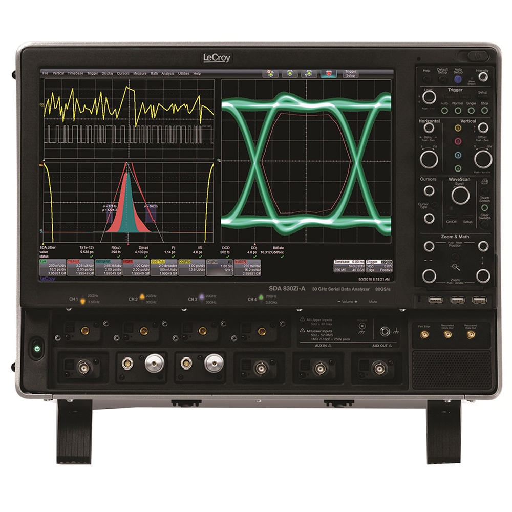
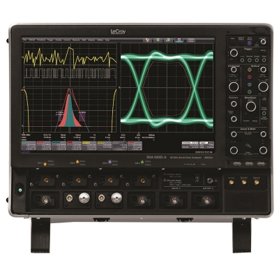
13 GHz, 40 GS/s, 4ch, 32 Mpts/Ch DSO with 15.3" WXGA Color Display. 50 ohm and 1 Mohm Inputs.
| Analog Bandwidth (Max) | 13 GHz |
| Analog Bandwidth @ 50 Ω (-3 dB) (ProLink Input) | 13 GHz (≥10 mV/div) |
| Analog Bandwidth @ 50 Ω (-3 dB) (ProBus Input) | 3.5 GHz (≥10 mV/div) |
| Analog Bandwidth @ 1 MΩ (-3 dB) (ProBus Input) | 500 MHz (typical, ≥2 mV/div) |
| Rise Time (10-90%, 50 Ω) | 32.5 ps (test limit, flatness mode) |
| Rise Time (20-80%, 50 Ω) | 24.5 ps (flatness mode) |
| Input Channels | 4 (Any combination of ProLink and ProBus inputs) |
| Bandwidth Limiters | 20 MHz, 200 MHz, 1 GHz, 4 GHz, 6 GHz, 8 GHz |
| Input Impedance | ProLink Inputs: 50 Ω+/-2% for ≤100 mV/div, 50 Ω+/-3% for >100 mV/div ProBus Inputs: 50 Ω+/-2% or 1 MΩ||16pF, 10 MΩ || 11 pF with supplied Probe |
| Input Coupling | ProLink Inputs - 50 Ω: DC, GND ProBus Inputs - 1 MΩ: AC, DC, GND; 50 Ω: DC, GND |
| Maximum Input Voltage | 50 Ω (ProLink): ±2 Vmax@≤100mV/div, 5.5Vrms@>100mV/div 50 Ω (ProBus): ±5 Vmax, 3.5 Vrms 1 MΩ (ProBus): 250 V max. (peak AC: < 10 kHz + DC) |
| Channel-Channel Isolation | DC to 10 GHz: 50 dB (>315:1) 10 to 15 GHz: 46 dB (>200:1) 15 to 20 GHz: 40 dB (>100:1) (For any two ProLink input channels, same or different v/div settings, typical) |
| Vertical Resolution | 8 bits; up to 11 bits with enhanced resolution (ERES) |
| Sensitivity | 50 Ω (ProLink): 2 mV-1 V/div, fully variable (2-9.9 mV/div via zoom) 50 Ω (ProBus): 2 mV-1 V/div, fully variable; 1 MΩ (ProBus): 2 mV-10 V/div, fully variable |
| DC Vertical Gain Accuracy (Gain Component of DC Accuracy) | ±1% F.S. (typical), offset at 0V; ±1.5% F.S. (test limit), offset at 0V |
| Offset Range | 50 Ω (ProLink): ±500 mV @ 2-100 mV/div ±4 V @ >100 mV/div -1 V/div 50 Ω (ProBus): ±750 mV @ 2-100 mV/div ±4 V @ >100 mV/div -1 V/div 1 MΩ: ±1V @ 2-140 mV/div ±10V @ 142mV-1.40V/div ±100V @ 1.42V-10V/div |
| Offset Accuracy | 50 Ω (ProLink): 2 mV-1 V/div, fully variable (2-9.9 mV/div via zoom) 50 Ω (ProBus): 2 mV-1 V/div, fully variable; 1 MΩ (ProBus): 2 mV-10 V/div, fully variable |
| DC Vertical Offset Accuracy | ±(1.5% of offset setting + 1.5% F.S. + 1 mV) (test limit) |
| Timebases | Internal timebase common to 4 input channels |
| Time/Division Range | 20 ps/div-128 s/div (Real-Time Mode: 20 ps/div - 64 s/div; RIS mode: 20 ps/div - 10 ns/div, user selectable at ≤10ns/div; Roll mode: 100 ms/div up to 128 s/div, user selectable at ≥100 ms/div and ≤5 MS/s), depending on memory length |
| Clock Accuracy | < 1 ppm + (aging of 0.5ppm/yr from last calibration) |
| Sample Clock Jitter | up to 10µs Acquired Time Range: 100fsrms (Internal Timebase Reference) up to 6.4ms Acquired Time Range: 150fsrms (Internal Timebase Reference) |
| Delta Time Measurement Accuracy | √2*√((Noise/SlewRate)^2+(Sample Clock Jitter)^2 ) (RMS)+(clock accuracy*reading)(seconds) |
| Jitter Measurement Floor | √((Noise/SlewRate)^2+(Sample Clock Jitter)^2 ) secondsrms (TIE) |
| Jitter Between Channels | <325fsrms (TIE, typical, measured at maximum bandwidth) |
| Trigger and Interpolator Jitter | <0.1 ps rms (typical, software assisted), 2 ps rms (typical, hardware), |
| Channel-Channel Deskew Range | ±9 x time/div. setting or 25 ns max. (whichever is larger), each channel |
| External Timebase Reference (Input) | 10 MHz; 50 Ω impedance, applied at the rear input |
| External Timebase Reference (Output) | 10 MHz; 50 Ω impedance, output at the rear |
| Single-Shot Sample Rate/Ch | 40 GS/s (80 GS/s on 2 Ch using optional WM8Zi-2X80GS External Interleaving Device) |
| Random Interleaved Sampling (RIS) | 200 GS/s for repetitive signals (20 ps/div to 10 ns/div) |
| Maximum Trigger Rate | 1,000,000 waveforms/second (in Sequence Mode, up to 4 channels) |
| Intersegment Time | 1 µs |
| Standard Memory (4 Ch / 2 Ch / 1Ch) (Number of Segments) | 32 M / 32 M / 32 M (Memory and Sample Rate can be doubled in 1 or 2 Ch mode with use of WM8Zi-2X80GS External Interleaving Device) (7500) |
| Memory Options (4 Ch / 2 Ch / 1Ch) (Number of Segments) |
M-64 Option: 64M / 64M / 64M (15,000) L-128 Option: 128M / 128M / 128M (15,000) VL-256 Option: 256M / 256M / 256M (15,000) Note: On all memory options, WM8Zi-2X80GS External Interleaving Device permits 80 GS/s on 1 or 2ch with twice the memory) |
| Averaging | Summed averaging to 1 million sweeps; continuous averaging to 1 million sweeps |
| Enhanced Resolution (ERES) | From 8.5 to 11 bits vertical resolution |
| Envelope (Extrema) | Envelope, floor, or roof for up to 1 million sweeps |
| Interpolation | Linear or Sin x/x |
| Modes | Normal, Auto, Single, and Stop |
| Sources | Any input channel, Aux, Aux/10, Line, or Fast Edge. Slope and level unique to each source (except line trigger) |
| Coupling Mode | DC, AC, HFRej, LFRej |
| Pre-trigger Delay | 0-100% of memory size (adjustable in 1% increments of 100 ns) |
| Post-trigger Delay | 0-10,000 divisions in real time mode, limited at slower time/div settings or in roll mode |
| Hold-off by Time or Events | From 2 ns up to 20 s or from 1 to 99,999,999 events |
| Internal Trigger Range | ±4.1 div from center |
| Trigger Sensitivity with Edge Trigger (1.85/2.4/2.92mm Inputs) | Not Applicable |
| Trigger Sensitivity with Edge Trigger ProBus Inputs | 2 div @ < 3.5 GHz, 1.5 div @ < 1.75 GHz, 1.0 div @ < 200 MHz, (for DC coupling, ≥ 10 mV/div, 50 Ω) |
| Trigger Sensitivity with Edge Trigger ProLink Inputs | 2 div @ < 13 GHz, 1.5 div @ < 3 GHz, 1.0 div @ < 200 MHz, (for DC, AC, LFRej coupling, ≥ 10 mV/div, 50 Ω) |
| External Trigger Sensitivity, (Edge Trigger) | 2 div @ < 1 GHz, 1.5 div @ < 500 MHz, 1.0 div @ < 200 MHz, (for DC coupling) |
| Max. Trigger Frequency, SMART Trigger | 2.0 GHz @ ≥ 10 mV/div (minimum triggerable width 200 ps) |
| External Trigger Input Range | Aux (±0.4 V); Aux/10 (±4 V) |
| Edge | Triggers when signal meets slope (positive, negative, or either) and level condition. |
| Window | Triggers when signal exits a window defined by adjustable thresholds |
| TV-Composite Video | Triggers NTSC or PAL with selectable line and field; HDTV (720p, 1080i, 1080p) with selectable frame rate (50 or 60 Hz) and Line; or CUSTOM with selectable Fields (1-8), Lines (up to 2000), Frame Rates (25, 30, 50, or 60 Hz), Interlacing (1:1, 2:1, 4:1, 8:1), or Synch Pulse Slope (Positive or Negative). |
| State or Edge Qualified | Triggers on any input source only if a defined state or edge occurred on another input source. Holdoff between sources is selectable by time or events. |
| Qualified First | In Sequence acquisition mode, triggers repeatably on event B only if a defined pattern, state, or edge (event A) is satisfied in the first segment of the acquisition. Holdoff between sources is selectable by time or events. |
| Dropout | Triggers if signal drops out for longer than selected time between 1 ns and 20 s. |
| Pattern | Logic combination (AND, NAND, OR, NOR) of 5 inputs (4 channels and external trigger input). Each source can be high, low, or don't care. The High and Low level can be selected independently. Triggers at start or end of the pattern. |
| Glitch | Triggers on positive or negative glitches with widths selectable as low as 200ps to 20 s, or on intermittent faults. |
| Width (Signal or Pattern) | Triggers on positive, negative, or both widths with widths selectable as low as 200ps to 20 s, or on intermittent faults. |
| Interval (Signal or Pattern) | Triggers on intervals selectable between 1 ns and 20 s. |
| Timeout (State/Edge Qualified) | Triggers on any source if a given state (or transition edge) has occurred on another source. Delay between sources is 1 ns to 20 s, or 1 to 99,999,999 events. |
| Runt | Trigger on positive or negative runts defined by two voltage limits and two time limits. Select between 1 ns and 20 ns. |
| Slew Rate | Trigger on edge rates. Select limits for dV, dt, and slope. Select edge limits between 1 ns and 20 ns. |
| Exclusion Triggering | Trigger on intermittent faults by specifying the expected behavior and triggering when that condition is not met |
| Capability | Arm on "A" event, then Trigger on "B" event. Or Arm on "A" event, then Qualify on "B" event, and Trigger on "C" event. |
| Types | Cascade A then B: Edge, Window, Pattern (Logic) Width, Glitch, Interval, Dropout, or Measurement. Measurement can be on Stage B only. Cascade A then B then C (Measurement): Edge, Window, Pattern (Logic), Width, Glitch, Interval, Dropout, or Measurement. Measurement can be on Stage C only. Cascade A then B then C: Edge, Window, Pattern (Logic) |
| Holdoff | Holdoff between A and B or B and C is selectable by time (1ns to 20s) or number of events. Measurement trigger selection as the last stage in a Cascade precludes a holdoff setting between the prior stage and the last stage. |
| Data Rates | Option WM8Zi-6GBIT-80B-8B10B-TD: 600 Mb/s to 6.5 Gb/s, Channel 4 input only Option WM8Zi-14GBIT-80B-8B10B-TD: 600 Mb/s to 14.1 Gb/s, Channel 4 input only |
| Pattern Length | 80 bits NRZ, eight 8b/10b symbols, 64b/66b symbol |
| Clock and Data Outputs | No Clock and Data Recovery outputs provided |
| Optionally available | I2C, SPI (SPI, SSPI, SIOP), UART-RS232, CAN, LIN, FlexRay, I2S (Audio), MIL-1553 |
| Measurement Trigger Capability | Select from a large number of measurement parameters trigger on a measurement value with qualified limits. Can be used as only trigger or last event in a Cascade Trigger. |
| Type | Color 15.3" flat panel TFT-Active Matrix LCD with high resolution touch screen |
| Resolution | WXGA; 1280 x 768 pixels. |
| Number of traces | Display a maximum of 16 traces (up to 40 with some software options). Simultaneously display channel, zoom, memory and math traces. |
| Grid Styles | Auto, Single, Dual, Quad, Octal, X-Y, Single+X-Y, Dual+X-Y |
| Waveform Representation | Sample dots joined, or sample dots only |
| Internal Waveform Memory | 12 active waveform memory traces (M1-M12) store 16 bit/point full length waveforms. Waveforms can be stored to any number of files limited only by the data storage media capacity. |
| Type | Supports touch screen integration of user-supplied second display with split-grid capability. (Note: touch screen driver for second display may not be a Fujitsu driver) |
| Resolution | Determined by display chosen by user |
| Intensity | 256 Intensity Levels, 1-100% adjustable via front panel control |
| Types | Select analog or color-graded |
| Number of Channels | up to 4 simultaneously |
| Max Sampling Rate | 40 GS/s (80 GS/s with optional WM8Zi-2X80GS external interleaving device) |
| Persistence Aging | Select from 500 ms to Infinity |
| Waveforms/second (continuous) | up to 2500 Waveforms/second |
| Operation | Front panel toggle between WaveStream ON (Analog), ON (Color) and OFF |
| Analog and Color-Graded Persistence | Variable saturation levels; stores each trace's persistence data in memory |
| Persistence Types | Select analog, color, or three-dimensional |
| Trace Selection | Activate persistence on all or any combination of traces |
| Persistence Aging | Select from 500 ms to infinity |
| Sweep Display Modes | All accumulated, or all accumulated with last trace highlighted |
| Type | LeCroy LSIB |
| Transfer Rate | up to 325 MB/s (typical) |
| Output Protocol | PCI Express, Gen 1 (4 lanes utilized for data transfer) |
| Control Protocol | TCP/IP |
| Command Set | Via Windows Automation, or via LeCroy Remote Command Set |
| Type | Intel® Core™ i7-4770S Quad, 3.1 GHz (up to 3.9 GHz in Turbo mode) (or better) |
| Processor Memory | 8 GB standard for STD memory (20 Mpt), S-32 and M-64 memory options 16 GB standard for L-128 and VL-256 memory options Up to 32 GB optional |
| Operating System | Microsoft Windows® 7 Professional Edition (64-bit) |
| Real Time Clock | Date and time displayed with waveform in hardcopy files. SNTP support to synchronize to precision internal clocks. |
| Zoom Expansion Traces | Display up to 12 Zoom and 12 Math/Zoom traces |
| Front Panel and Instrument Status | Store to the internal hard drive, over the network, or to a USB-connected peripheral device. |
| Remote Control | Via Windows Automation, or via LeCroy Remote Command Set |
| Network Communication Standard | VXI-11 or VICP, LXI Class C (v1.2) Compliant |
| GPIB Port | Supports IEEE - 488.2 |
| LSIB Port (optional) | Supports PCIe Gen1 x4 protocol with LeCroy supplied API |
| Ethernet Port | Supports 10/100/1000BaseT Ethernet interface (RJ45 port) |
| USB Ports | 4 rear USB 3.0 ports, 3 front panel USB 2.0 ports support Windows compatible devices |
| External Monitor Port | Full-size DisplayPort connnector Includes support for extended desktop operation with second monitor. |
| Peripheral Bus | LeCroy LBUS standard |
| Signal Types | For External Trigger Input |
| Coupling | 50 Ω: DC; 1 MΩ: AC, DC, GND |
| Max. Input Voltage | 50 Ω: 5 Vrms; 1 MΩ: 250 V (Peak AC < 10 kHz + DC) |
| Signal Types | Select from calibrator, control signals or Off |
| Output Signal | 500 Hz-5 MHz square wave or DC level; 0.0 to 500 mV into 50 Ω (0-1 V into 1 MΩ) |
| Control Signals | Trigger enabled, trigger out, pass/fail status, off |
| Connector Type | BNC, located on front |
| Auto Setup | Automatically sets timebase, trigger, and sensitivity to display a wide range of repetitive signals |
| Find Vertical Scale | Automatically sets the vertical sensitivity and offset for the selected channel to display a waveform with the maximum dynamic range |
| Auto Calibration | Ensures specified DC and timing accuracy is maintained for 1 year minimum. |
| Probes | Qty. (4) ÷10 Passive Probes |
| Probe System | Probus and ProLink. Automatically detects and supports a variety of compatible probes |
| Scale Factors | Automatically or manually selected depending on probe used |
| Calibration Output | Cal Output: 1kHz square wave, 1Vp-p (typical), output to probe hook. |
| Voltage | 100-240 VAC ±10% at 45-66 Hz; 100-120 VAC ±10% at 380-420 Hz; Automatic AC Voltage Selection, Installation Category II |
| Max. Power Consumption | 975 W / 975 VA |
| Temperature (Operating) | +5 °C to +40 °C |
| Temperature (Non-Operating) | -20 °C to +60 °C |
| Humidity (Operating) | 5% to 80% relative humidity (non-condensing) up to +31 °C. Upper limit derates to 50% relative humidity (non-condensing) at +40 °C. |
| Humidity (Non-Operating) | 5% to 95% relative humidity (non-condensing) as tested per MIL-PRF-28800F |
| Altitude (Operating) | Up to 10,000 ft. (3048 m) at or below +25 °C |
| Altitude (Non-Operating) | Up to 40,000 ft. (12,192 m) |
| Random Vibration (Operating) | 0.5 grms 5 Hz to 500 Hz, 15 minutes in each of three orthogonal axes |
| Random Vibration (Non-Operating) | 2.4 grms 5 Hz to 500 Hz, 15 minutes in each of three orthogonal axes |
| Functional Shock | 20 g peak, half sine, 11 ms pulse, 3 shocks (positive and negative) in each of three orthogonal axes, 18 shocks total |
| Dimensions (HWD) | 14"H x 18.4"W x 16"D (355 x 467 x 406 mm) |
| Weight | 51.5 lbs. (23.4 kg) |
| Shipping Weight | 70.0 lbs. (31.8 kg) |
| Certifications | CE Compliant, UL and cUL listed; conforms to EN 61326, EN 61010-1, EN61010-2-030, UL 61010-1 3rd edition, and CSA C22.2 No. 61010-1-12 |
| Warranty and Service | 3-year warranty; calibration recommended annually. Optional service programs include extended warranty, upgrades, and calibration services. |